
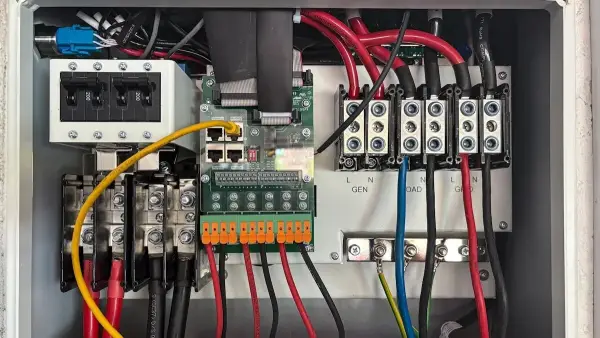
Modern frequency converter systems deliver precise motor speed control, exceptional energy efficiency, and reliable power conditioning across industrial operations. By converting fixed-frequency alternating current into a continuously adjustable frequency and voltage output, these systems allow machinery to adapt instantly to changing mechanical loads. Replacing rigid direct-line motor setups with advanced frequency conversion reduces mechanical wear, slashes utility costs, and extends equipment service life. Understanding the core internal architecture reveals how these sophisticated power electronics manage heavy industrial power with extreme accuracy.
The Rectifier Stage: Converting AC to DC
The primary operational stage of a rotary frequency converter begins at the rectifier, which receives fixed alternating current from the local power grid and converts it into direct current. Modern industrial converters utilize solid-state semiconductor devices, such as insulated-gate bipolar transistors or silicon carbide diodes, to execute this conversion with minimal energy loss.
Converting incoming power to direct current creates a manageable baseline that isolates the downstream equipment from grid voltage fluctuations and transient surges. Advanced active front-end rectifiers also manage harmonic distortion, preventing electrical noise from feeding back into the primary facility grid. This clean initial conversion guarantees that the internal power stages receive stable, predictable energy regardless of external supply conditions.
The DC Bus: Energy Storage and Signal Smoothing
Once the rectifier converts incoming power, the energy flows directly into the intermediate direct current link, commonly known as the DC bus. This central stage acts as a high-capacity reservoir, utilizing heavy-duty film or electrolytic capacitors alongside high-inductance chokes to smooth out ripple voltage generated during rectification.
The DC bus absorbs sudden load spikes and buffers energy fluctuations between input and output stages. In applications involving heavy braking or rapid deceleration, regenerated energy feeds back from the motor into the DC link. Advanced converter systems pair the DC bus with dynamic braking choppers or regenerative feedback units, converting excess kinetic energy back into usable electricity or dissipating it safely.
The Inverter Stage: Precise Variable-Frequency Output
The inverter stage forms the core engine of output power synthesis, taking filtered direct current from the DC bus and converting it back into a precise three-phase alternating current. High-speed semiconductor switches pulse thousands of times per second using pulse-width modulation techniques to construct smooth, synthetic sine waves at any desired frequency.
Modulating pulse widths allows the system to vary output voltage and frequency simultaneously, maintaining optimal magnetic flux inside connected electric motors. This precise control allows industrial machinery to ramp speed smoothly from a complete stop up to full operating speed without experiencing the extreme inrush currents associated with direct-on-line starting. Smooth acceleration protects gearboxes, belts, and mechanical couplings from severe mechanical stress.
Thermal Management and Enclosure Protection
Managing thermal dissipation is essential for maintaining component reliability, as high-power semiconductors generate significant heat during high-frequency switching. Modern frequency converters employ heavy-duty aluminum heat sinks paired with variable-speed cooling fans that scale airflow based on real-time internal temperatures. High-capacity industrial models often utilize sealed liquid-cooling channels to handle intense thermal loads within compact footprints.
Protecting internal power electronics from harsh industrial environments requires robust enclosure design. Advanced conformal coatings shield delicate printed circuit boards from conductive dust, moisture, and chemical vapors commonly found in manufacturing facilities. Proper thermal design paired with physical environmental protection ensures long-term operational availability in demanding industrial settings.
Output Filtering and Motor Protection
Connecting long cable runs between a frequency converter and a motor can create steep voltage spikes due to high-speed switching frequencies. Integrated output filters, such as sine-wave filters and dv/dt reactors, smooth out the pulse-width modulated waveform before it leaves the converter enclosure.
Filtering the output power reduces voltage stress on motor winding insulation, lowers operating temperatures, and suppresses high-frequency bearing currents. Protecting the motor’s electrical and mechanical components prevents premature insulation breakdown, ensuring that both the drive and the connected motor operate reliably over extended lifespans.
Conclusion
A modern frequency converter system relies on the seamless coordination of its rectifier, DC bus, inverter, and digital control stages to deliver superior motor management. Converting raw grid power into clean, adjustable energy optimizes process control while shielding mechanical equipment from unnecessary strain. Investing in advanced frequency conversion technology lowers utility consumption, minimizes maintenance downtime, and provides the operational flexibility required by automated industrial facilities. Understanding these key components ensures proper selection, integration, and long-term performance across any automated drive application.